Yamaha MBK YQ100 Service Manual Page 4
- Page / 232
- Table of contents
- TROUBLESHOOTING
- BOOKMARKS
- 5ME1-AE1 1
- CAUTION: 3
- HOW TO USE THIS MANUAL 4
- EAS00009 5
- EAS00011 6
- CHAPTER 1 8
- GENERAL INFORMATION 8
- IMPORTANT INFORMATION 10
- CHECKING THE CONNECTIONS 12
- SPECIAL TOOLS 14
- EAS00027 14
- CHAPTER 2 17
- SPECIFICATIONS 17
- GENERAL SPECIFICATIONS 19
- MAINTENANCE SPECIFICATIONS 21
- TIGHTENING TORQUES 24
- GENERAL TORQUE SPECIFICATIONS 31
- GENERAL TIGHTENING TORQUE 31
- EAS00031 32
- EAS00032 33
- CABLE ROUTING 34
- EAS00035 34
- CHAPTER 3 43
- Every 12,000 km 44
- Every 20,000 km 45
- 3 Nm (0,3 m.kg) 50
- 3 Nm (0,3m.kg) 50
- 4 Nm (0,4 m.kg) 52
- 322025(b) 54
- EAS00058 55
- CHECKING THE SPARK PLUG 56
- CHECKING THE ENGINE OIL LEVEL 58
- AUTOLUBE PUMP AIR BLEEDING 59
- AUTOLUBE PUMP AIR BLEEDING/ 60
- ADJUSTING THE FRONT BRAKE/ 62
- ADJUSTING THE REAR BRAKE 62
- EAS00116 63
- CHECKING THE BRAKE SHOES/ 64
- WARNING 65
- CHECKING THE FRONT FORK 67
- EAS00165 68
- CHECKING THE TIRES 68
- CHECKING THE WHEELS/ 70
- LUBRICATING THE CENTERSTAND/ 71
- CHECKING THE BATTERY 72
- ELECTRICAL SYSTEM 72
- CHECKING THE BATTERY/ 75
- CHECKING THE FUSE 75
- CHECKING THE FUSE/ 76
- REPLACING THE HEADLIGHT BULB 76
- REPLACING THE HEADLIGHT BULB/ 77
- ADJUSTING THE HEADLIGHT BEAM 77
- CHAPTER 4 79
- OVERHAULING THE ENGINE 79
- OVERHAULING THE ENGINE 81
- EAS00192 84
- CYLINDER HEAD 86
- EAS00222 86
- 52.002~52.012mm 89
- 52.10 mm 89
- SECONDARY SHEAVE 98
- V-BELT, CLUTCH AND 100
- SECONDARY/PRIMARY SHEAVE 100
- INSPECTION AND REPAIR 109
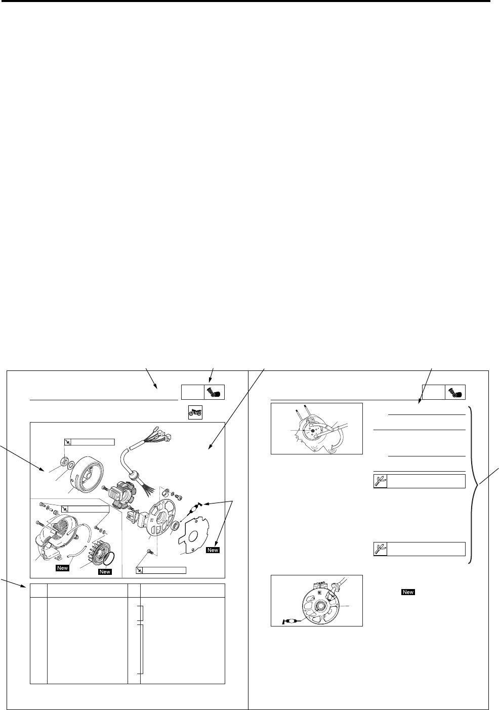
- C.D.I. MAGNETO 110
- ENGINE DISASSEMBLY 111
- AUTOLUBE PUMP 112
- TRANSMISSION 114
- EAS00423 116
- CRANKCASE AND REED VALVE 117
- CRANKSHAFT 122
- CHAPTER 5 126
- CARBURETOR 126
- EAS00480 127
- EAS000483 128
- EAS00487 131
- EAS00492 132
- FUEL COCK 133
- REED VALVE 134
- REED VALVE 134
- YP600051 135
- CHAPTER 6 137
- FRONT WHEEL AND BRAKE DISC 139
- EAS00513 139
- EAS00518 140
- EAS00520 141
- EAS00523 141
- EAS00525 142
- EAS00528 144
- 23 Nm (2,3 m.kg) 145
- EAS00548 147
- REAR WHEEL AND BRAKE 149
- EAS00555 149
- EAS00565 151
- EAS00569 151
- FRONT BRAKE 154
- EAS00576 154
- EAS00579 155
- EAS00584 157
- 1.2 Nm (0.12 m.kg) 158
- EAS00588 159
- EAS00590 159
- EAS00596 160
- EAS00612 162
- EAS00614 163
- EAS00631 165
- EAS00635 166
- EAS00646 168
- FRONT FORK 168
- EAS00654 170
- EAS00656 171
- EAS00659 172
- 60 Nm (6,0 m.kg) 175
- EAS00666 177
- EAS00668 177
- HANDLEBAR 177
- EAS00673 178
- STEERING HEAD 180
- EAS00675 180
- REAR SHOCK ABSORBER ASSEMBLY 184
- EAS00695 185
- CHAPTER 7 187
- ELECTRICAL 187
- CIRCUIT DIAGRAM 189
- ELECTRICAL COMPONENTS 190
- SWITCH INSPECTION 192
- A Starter switch 194
- IGNITION AND STARTING SYSTEM 195
- Ω (20°C) 196
- Ω at 20°C 197
- IGNITION AND STARTER SYSTEM 200
- STARTER MOTOR 201
- CHARGING SYSTEM 204
- LIGHTING SYSTEM 208
- 21W / 5W 213
- SIGNAL SYSTEM 215
- CHAPTER 8 224
- TROUBLESHOOTING 224
- POOR IDLE SPEED PERFORMANCE 226
- FAULTY AUTOMATIC 227
- FAULTY AUTOMATIC/ 228
- OVER HEATING 228
- IMPROPER KICKING/ 229
- FAULTY BRAKE 229
- IMPROPER KICKING 229
- YQ100 WIRING DIAGRAM 232
Related products and manuals for Scooters Yamaha MBK YQ100
 (294 pages)
(28 pages)
(63 pages)
(84 pages)
(72 pages)
(80 pages)
(80 pages)
(68 pages)
(294 pages)
(28 pages)
(63 pages)
(84 pages)
(72 pages)
(80 pages)
(80 pages)
(68 pages)
 (38 pages)
(68 pages)
(78 pages)
(38 pages)
(68 pages)
(78 pages)
 (6 pages)
(28 pages)
(13 pages)
(6 pages)
(28 pages)
(13 pages)
 (1 pages)
(80 pages)
(1 pages)
(80 pages)
© 2020, manymanuals.com. All rights reserved. | 0.958 s |
 Manymanuals.com
 Manymanuals.de
 Manymanuals.fr
 Manymanuals.it
 Manymanuals.pl
 Manymanuals.cz
 Manymanuals.es
 Manymanuals-pt.com
Comments to this Manuals