Yamaha QL5 Owner's Manual Page 43
- Page / 264
- Table of contents
- BOOKMARKS
- Reference Manual 1
- Contents 2
- Function Tree 4
- SELECTED CHANNEL section 10
- Reference Manual 10
- Channel Strip section 11
- TO STEREO/MONO field 13
- 1 TO STEREO PAN knob 13
- 2 ST/MONO indicator 13
- DCA group field 13
- Mute group field 13
- Input and output patching 14
- PATCH/NAME screen 15
- 4 Category select list 16
- 5 Port select buttons 16
- 7 Close button 16
- CH SELECT screen 18
- INSERT screen (8ch) 19
- DIRECT OUT screen (8ch) 22
- Input channels 23
- 2 Icon select buttons 25
- 3 Sample name setup buttons 25
- When selecting the NAME tab 25
- Making HA (Head Amp) settings 26
- GAIN/PATCH window (8ch) 27
- GAIN/PATCH window 29
- STEREO/MONO bus 30
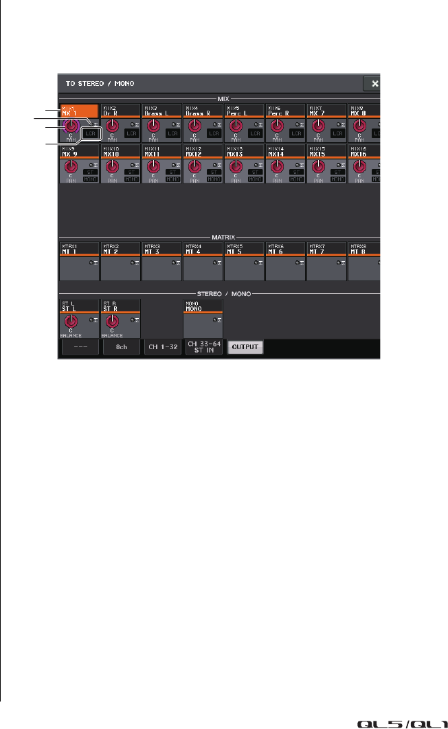
- TO STEREO/MONO window (8ch) 31
- TO STEREO/MONO window 32
- MATRIX bus 34
- MIX SEND/MATRIX SEND window 35
- 8 SEND PAN/BALANCE knob 36
- 9 SEND LEVEL knob 36
- SENDS ON FADER mode 37
- INPUT DELAY window (8ch) 38
- Channel library operations 39
- OUTPUT channels 40
- MONO bus 42
- MONO channels to MATRIX buses 44
- 7 SEND ON/OFF button 45
- OUTPUT PORT screen 46
- 6 DELAY button 47
- 7 Ø (Phase) button 47
- 8 GAIN knob 47
- 9 Level meter 47
- EQ and Dynamics 49
- HPF/EQ window (8ch) 51
- Using dynamics 52
- CHANNEL VIEW screen 52
- DYNAMICS1/2 window (8ch) 54
- ST IN (QL1), OUTPUT) 54
- EQ library 55
- Dynamics library 55
- Channel Job 56
- Mute group 58
- Using mute groups 60
- Using the Mute Safe function 60
- RECALL SAFE MODE window 61
- A CLOSE button 63
- Channel Link function 64
- CH LINK MODE window 65
- CH LINK SET window 66
- 5 CLOSE button 67
- CH COPY MODE window 68
- CH MOVE MODE window 69
- CH DEFAULT MODE window 70
- Scene memory 71
- Storing and recalling scenes 72
- SCENE LIST window 73
- Recalling a scene 74
- Editing scene memories 75
- Scene memory editing 76
- Copying and pasting a scene 77
- Clearing a scene 77
- Cutting a scene 77
- Inserting a scene 77
- GLOBAL PASTE window 78
- FOCUS RECALL window 81
- Using the Fade function 82
- FADE TIME window 83
- 1 GPI OUT CONTROL buttons 84
- 2 CURRENT SETTING field 84
- SONG SELECT window 85
- Using Preview mode 86
- Monitor and Cue functions 87
- Using the Monitor function 88
- MONITOR window 89
- Using the Cue function 91
- Operating the Cue function 92
- MONITOR screen 93
- CUE window 94
- 5 Meter field 95
- 6 CUE OUTPUT button 95
- 7 CUE LEVEL knob 95
- 8 ACTIVE CUE indicator 95
- 9 CLEAR CUE button 95
- Talkback and Oscillator 96
- TALKBACK window 97
- Using the Oscillator function 98
- INTERVAL 99
- 3 ASSIGN section 100
- 4 Meter section 100
- 5 OSCILLATOR OUTPUT button 100
- INPUT METER screen 101
- OUTPUT METER screen 101
- INPUT/OUTPUT tabs 101
- Fader level and meter display 102
- METERING POINT field 102
- PEAK HOLD button 102
- About the virtual rack 103
- Virtual rack operations 103
- VIRTUAL RACK window 104
- 5 OUTPUT PATCH button 105
- 6 Rack container 105
- RACK MOUNTER window 106
- Inserting a GEQ in a channel 107
- GEQ EDIT window 107
- Using the 31BandGEQ 108
- GEQ EDIT window (31BandGEQ) 108
- Using the Flex15GEQ 108
- About AUTOMIXER 109
- Using Automixer 110
- STEREO type effects 112
- MIX type effects 112
- EFFECT EDIT window 114
- Using the Tap Tempo function 116
- Using the Freeze effect 118
- Using the Premium Rack 119
- Mounting a processor 120
- 1 ASSIST button 120
- 2 LIBRARY button 120
- 3 DEFAULT button 120
- GEQ library 126
- Effect library 126
- Premium Rack library 126
- Using an I/O device 127
- DANTE INPUT PATCH window 128
- PORT SELECT window 128
- OUTPUT PATCH window 129
- I/O DEVICE screen (Rio page) 130
- Remotely controlling an amp 131
- I/O DEVICE screen (AMP page) 132
- 3 DANTE SETUP button 133
- Daisy chain network 134
- Ring connection 134
- 1 EXTERNAL HA field 135
- 2 ID/Model name/+48V master 135
- 3 Virtual racks 135
- EXTERNAL HA window 136
- INTERNAL HA window 137
- Basic MIDI settings 138
- 1 TERMINAL field 140
- 2 PORT NO. field 140
- 3 OK button 140
- 1 CH field 140
- 2 OK button 140
- 1 PROGRAM CHANGE field 141
- 2 PROGRAM CHANGE MODE field 141
- MIDI PROGRAM CHANGE window 142
- MIDI CONTROL CHANGE window 145
- Recorder 146
- CH SELECT window 147
- 3 4A0987 5 6 148
- RECORDER screen 150
- Editing the title list 151
- Required devices and software 152
- Word clock settings 153
- Dante Accelerator settings 153
- Setting up Dante Controller 154
- Setting up DAW software 154
- Audio recording and playback 154
- Preparing the project 155
- Recording into a project 155
- NUENDO LIVE SETUP window 156
- Playing a multi-track project 158
- About the SETUP screen 159
- User settings 160
- CREATE USER KEY window 162
- Logging-in 163
- Changing the password 164
- Changing the user level 165
- USER SETUP window 166
- Preferences 167
- 5 PANEL OPERATION field 168
- USER DEFINED keys 169
- USER DEFINED knobs 173
- Custom fader bank 175
- Locking the console 176
- Unlocking the console 177
- SAVE/LOAD window 178
- SAVE SELECT screen 179
- LOAD SELECT screen 181
- 1 2 3 4 5 182
- Formatting a USB flash drive 183
- Word clock and slot settings 184
- WORD CLOCK/SLOT window 185
- About cascade connections 186
- 2 CASCADE LINK MODE buttons 187
- BUS SETUP window 189
- 1 2 3 4 5 6 7 190
- Setting the network address 191
- NETWORK window 192
- 5 hops = 0.5 ms 196
- DANTE SETUP window 197
- 1 DEVICE LABEL 199
- 2 INPUT/OUTPUT knobs 199
- 3 Device label entry keyboard 199
- REMOTE HA settings 200
- REMOTE HA SELECT window 200
- Displaying the device status 201
- Messages 201
- Error messages 202
- Warning messages 202
- Using GPI IN 203
- MIDI/GPI screen (GPI page) 204
- Using GPI OUT 204
- Using FADER START 206
- 4 THRESHOLD field 207
- 5 MODE field 207
- Help function 208
- Other functions 210
- ∞ dB (all the way down) 211
- EXIT button 214
- Warning/Error Messages 215
- Data List 220
- EQ Library List 221
- DYNAMICS Library List 222
- Data List 223
- * At fs=44.1 kHz 223
- Dynamics Parameters 224
- COMPRESSOR 225
- EXPANDER 225
- Effect Type List 226
- Effects Parameters 227
- STEREO REVERB 228
- EARLY REF 228
- GATE REVERB, REVERSE GATE 228
- MONO DELAY 228
- STEREO DELAY 228
- MOD. DELAY 229
- DELAY LCR 229
- CHORUS 229
- FLANGE 230
- SYMPHONIC 230
- PHASER 230
- DYNA.FLANGE 230
- DYNA.PHASER 231
- HQ.PITCH 231
- DUAL PITCH 231
- TREMOLO 231
- AUTOPAN 232
- ROTARY 232
- RING MOD 232
- MOD.FILTER 232
- DYNA.FILTER 232
- REV+CHORUS 233
- REVCHORUS 233
- REV+FLANGE 233
- REVFLANGE 233
- REV+SYMPHO 234
- REVSYMPHO 234
- REVPAN 234
- DELAY+ER 234
- DELAYER 235
- DELAY+REV 235
- DELAYREV 235
- DISTDELAY 236
- MULTI FILTER 236
- FREEZE 236
- DISTORTION 236
- AMP SIMULATE 237
- COMP276 237
- COMP276S 237
- COMP260 237
- COMP260S 237
- EQUALIZER601 238
- OPENDECK 238
- M.BAND DYNA 238
- M.BAND COMP 239
- Portico5033 239
- Portico5043 239
- Opt-2A 240
- Dynamic EQ 240
- Automixer Parameters 240
- NRPN parameter assignments 243
- Input channels 247
- MIX Channels 249
- MATRIX Channels 250
- STEREO, MONO Channels 251
- MIDI Data Format 252
- 2 SYSTEM REALTIME MESSAGE 253
- 3 SYSTEM EXCLUSIVE MESSAGE 253
- 4 PARAMETER CHANGE details 254
- 4.5 EXIST LIBRARY RANGE 256
- 4.7 FUNCTION CALL – MODULE – 257
- 4.9 LEVEL METER DATA 258
- Input/Output Specifications 259
- Electrical characteristics 260
- Mixer Basic Parameters 261
- MIDI Implementation Chart 263
Related products and manuals for Audio mixers Yamaha QL5


 (32 pages)
(15 pages)
(14 pages)
(32 pages)
(15 pages)
(14 pages)
 (52 pages)
(40 pages)
(76 pages)
(42 pages)
(16 pages)
(24 pages)
(50 pages)
(24 pages)
(40 pages)
(14 pages)
(2 pages)
(51 pages)
(40 pages)
(24 pages)
(14 pages)
(48 pages)
(24 pages)
(52 pages)
(40 pages)
(76 pages)
(42 pages)
(16 pages)
(24 pages)
(50 pages)
(24 pages)
(40 pages)
(14 pages)
(2 pages)
(51 pages)
(40 pages)
(24 pages)
(14 pages)
(48 pages)
(24 pages)
© 2020, manymanuals.com. All rights reserved. | 0.730 s |
 Manymanuals.com
 Manymanuals.de
 Manymanuals.fr
 Manymanuals.it
 Manymanuals.pl
 Manymanuals.cz
 Manymanuals.es
 Manymanuals-pt.com
Comments to this Manuals