Yamaha LSI YMF715 Technical Information Page 171
- Page / 204
- Table of contents
- BOOKMARKS
- 390 Series390 Series 1
- CopyrightCopyright 2
- DisclaimerDisclaimer 2
- Manual Structure 3
- Conventions 4
- Chapter 3 BIOS Setup Utility 7
- List of Figures 9
- List of Tables 11
- System Introduction 13
- 1.2 System Board Layout 14
- System Introduction 1-3 15
- 1.2.2 CPU Board 16
- 1.2.3 Audio Board 17
- 1.2.4 Battery Board 17
- 1.2.5 Keyboard/Touchpad Board 18
- 1.3 Jumpers and Connectors 19
- 1-8 Service Guide 20
- Table 1-2 SW1 Switch Settings 20
- 1.4.1 Memory Address Map 21
- 1.4.2 Interrupt Channel Map 21
- 1.4.3 DMA Channel Map 22
- 1.4.4 I/O Address Map 22
- • Memory bus width: 64-bit 23
- 1.4.8 Second-Level Cache 24
- 1.4.9 Video Memory 25
- 1.4.10 Video 25
- 1.4.11 Parallel Port 26
- 1.4.12 Serial Port 27
- 1.4.13 Audio 27
- 1.4.14 PCMCIA 27
- 1.4.15 Touchpad 28
- 1.4.16 Keyboard 28
- 1.4.17 FDD 29
- 1.4.18 HDD 30
- 1.4.19 CD-ROM 30
- • Rapid mode 31
- • Charge-in-use mode 31
- • Trickle mode 31
- 1.4.22 DC-DC Converter 32
- 1.4.23 DC-AC Inverter 33
- 1.4.24 LCD 33
- 1.4.25 AC Adapter 34
- 1.5.1 BIOS 35
- STANDBY MODE 37
- LIGHT GREEN MODE 38
- HIBERNATION MODE 38
- DISPLAY STANDBY MODE 39
- • Flash power LED with 1 Hz 40
- • Windows 95 41
- Name Function Location 42
- 1.6 Block Diagrams 43
- 1.6.2 Clock 44
- System Introduction 1-33 45
- 1.8 Mechanical Specifications 46
- Major Chips Description 47
- 2.1.1 Features 48
- 2.1.2 Block Diagram 50
- 2.1.3 Terminal Functions 51
- 2-6 Service Guide 52
- Major Chips Description 2-7 53
- 2-8 Service Guide 54
- Major Chips Description 2-9 55
- 2-10 Service Guide 56
- Major Chips Description 2-11 57
- 2-12 Service Guide 58
- Major Chips Description 2-13 59
- 2-14 Service Guide 60
- Major Chips Description 2-15 61
- 2-16 Service Guide 62
- Major Chips Description 2-17 63
- 2-18 Service Guide 64
- Major Chips Description 2-19 65
- 2.2.1 M1531 66
- • Enhanced Power Management 68
- Major Chips Description 2-23 69
- 2.2.1.2 Pin Diagram 69
- 2-24 Service Guide 70
- 2.2.1.3 Signal Descriptions 70
- Major Chips Description 2-25 71
- 2-26 Service Guide 72
- Major Chips Description 2-27 73
- 2-28 Service Guide 74
- 2.2.1.4 Numerical Pin List 74
- Major Chips Description 2-29 75
- 2-30 Service Guide 76
- Major Chips Description 2-31 77
- 2-32 Service Guide 78
- Major Chips Description 2-33 79
- 2.2.2 M1533 80
- • Built-in PCI IDE controller 84
- • USB interface 84
- • SMBus interface 84
- Major Chips Description 2-39 85
- 2.2.2.2 Pin Diagram 85
- 2-40 Service Guide 86
- 2.2.2.3 Numerical Pin List 86
- Major Chips Description 2-41 87
- 2-42 Service Guide 88
- Major Chips Description 2-43 89
- 2-44 Service Guide 90
- Major Chips Description 2-45 91
- 2-46 Service Guide 92
- 2.3.1 Features 93
- • Serial Ports 94
- • Infrared Port 94
- • ISA Host Interface 94
- 2.3.2 General Description 95
- 2.3.3 Pin Configuration 96
- Major Chips Description 2-51 97
- 2.3.4 Pin Descriptions 98
- Major Chips Description 2-53 99
- BUFFER TYPE DESCRIPTIONS 100
- Major Chips Description 2-55 101
- 2.3.6 Block Diagram 102
- 2.4.1 Features 103
- • Drivers Features 105
- • Multimedia Software 105
- • Software Utilities 105
- • Software Documentation 105
- • Software Support 106
- • BIOS Features 106
- • System BIOS Hooks 106
- • BIOS Modify Program (BMP) 106
- 2.4.3 Introduction / Overview 107
- • PCI Bus 109
- • Display Memory Interface 110
- Major Chips Description 2-65 111
- 2-66 Service Guide 112
- 2.4.4.4 Pin Functions 112
- Table 2-8 65555 Pin Functions 112
- Major Chips Description 2-67 113
- MVCC and GND 113
- 2-68 Service Guide 114
- Major Chips Description 2-69 115
- 2-70 Service Guide 116
- Major Chips Description 2-71 117
- 2-72 Service Guide 118
- Major Chips Description 2-73 119
- 2-74 Service Guide 120
- Major Chips Description 2-75 121
- 2-76 Service Guide 122
- 2.5.1 Overview 123
- 2.5.2 Description 123
- 2.5.3 Pin Configuration 124
- 2.5.4 Pin Descriptions 125
- Functional Block Diagram 126
- 2.6.1 Features 127
- 2.6.2 Pin Diagram 128
- Multi-purpose Dins: 13 pins 129
- 2-84 Service Guide 130
- BIOS Setup Information 131
- 3-2 Service Guide 132
- 3.1 Basic System Settings 133
- 3.2 Startup Configuration 134
- BIOS Setup Information 3-5 135
- BIOS Setup Information 3-7 137
- 3.4 System Security 138
- 3.5 Power Management Settings 139
- 3.6 Load Default Settings 141
- 4.1.1 Before You Begin 142
- 4-2 Service Guide 143
- 4.1.2 Connector Types 144
- 4.1.3 Disassembly Sequence 145
- 4.2 Installing Memory 147
- 4.3 Removing the Modem Board 149
- 4.5 Removing the Keyboard 151
- 4.6.2 Removing the Display 154
- 4.6.4 Replacing the CPU 156
- 4.6.5 Detaching the Top Cover 157
- 4.6.6 Removing the Mainboard 158
- REMOVING THE CHARGER BOARD 160
- REMOVING THE PCMCIA SOCKETS 160
- REMOVING THE AUDIO BOARD 161
- REMOVING THE TOUCHPAD 162
- REMOVING THE SPEAKERS 162
- 4.7 Disassembling the Display 163
- 4-24 Service Guide 165
- Model Number Definition 166
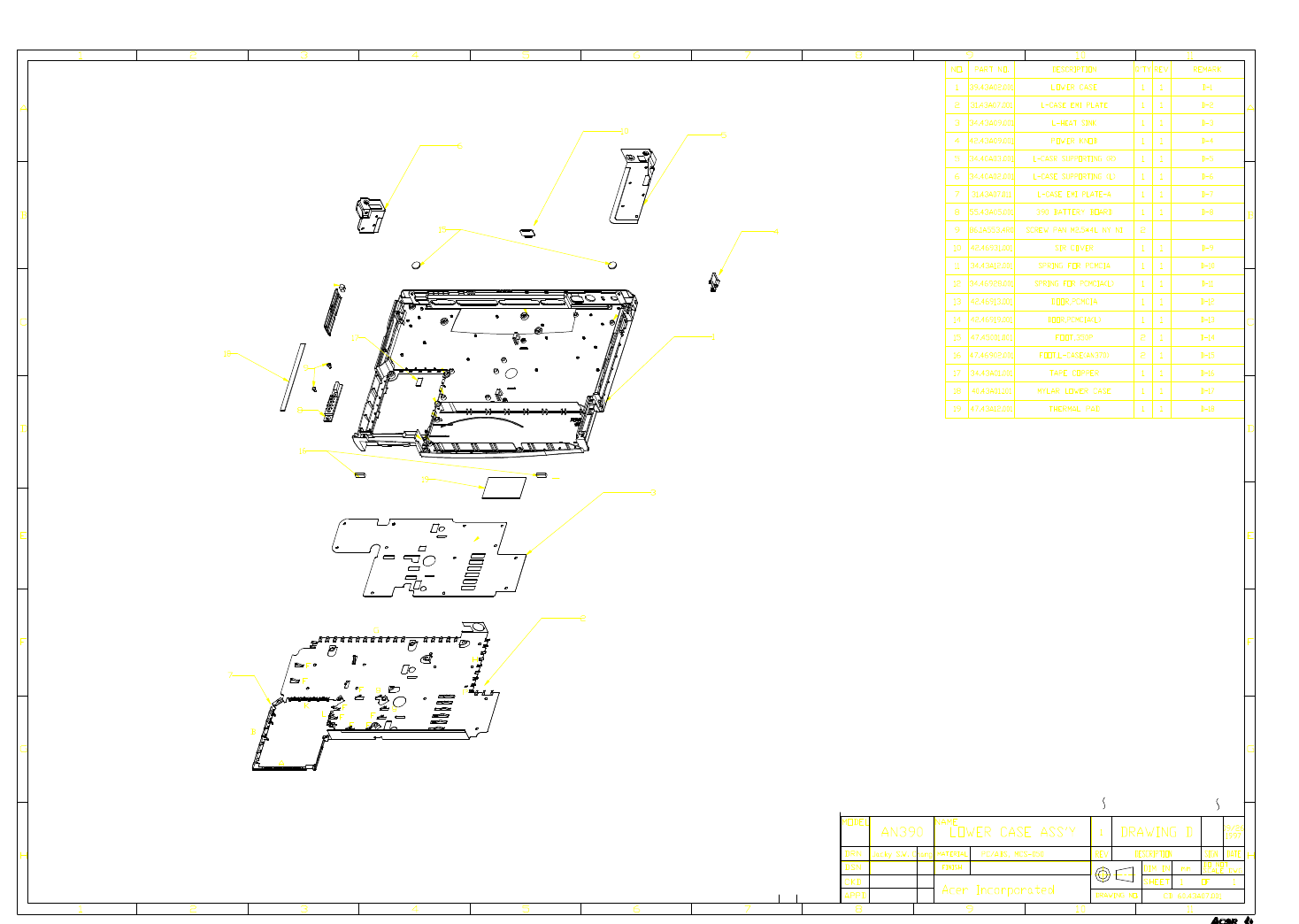
- Exploded View Diagram 167
- Spare Parts List 174
- C-2 Service Guide 175
- Table C-1 Spare Parts List 175
- Spare Parts List C-3 176
- C-4 Service Guide 177
- Schematics 178
- CPU BD TO BD CONNECTOR 179
- ALADDIN IV 181
- M1533 BYPASS CAPACITORS 182
- 256K L2 PIPELINE BURST CACHE 183
- VCCP BYPASS CAP 189
- VCC BYPASS CAP 189
- Serial Port COM1 193
- FAN conn 194
- BIOS POST Checkpoints 202
- E-2 Service Guide 203
- BIOS POST Checkpoints E-3 204
Related products and manuals for Motherboards Yamaha LSI YMF715


 (4 pages)
(64 pages)
(4 pages)
(64 pages)
© 2020, manymanuals.com. All rights reserved. | 1.393 s |
 Manymanuals.com
 Manymanuals.de
 Manymanuals.fr
 Manymanuals.it
 Manymanuals.pl
 Manymanuals.cz
 Manymanuals.es
 Manymanuals-pt.com
Comments to this Manuals