Yamaha DPX-530 Owner's Manual Page 9
- Page / 42
- Table of contents
- TROUBLESHOOTING
- BOOKMARKS
- Digital Cinema Projector 1
- Projecteur Cineme Numerique 1
- IMPORTANT SAFETY INSTRUCTIONS 2
- European compliance notice 4
- For U.K. customers 4
- IMPORTANT 4
- Table of contents 5
- Preparation1 6
- ◆ Accessory check 7
- Important 8
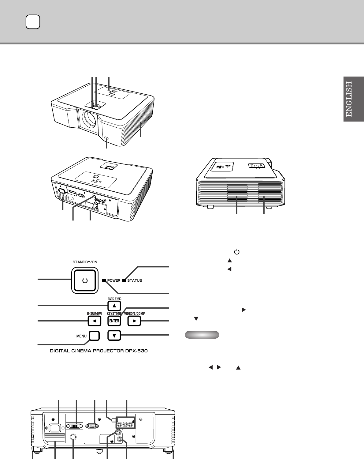
- Controls and functions2 9
- ◆ Remote control overview 10
- Using the remote control3 11
- Setting up the projector4 12
- Connections5 14
- ◆ Connecting to a DVD player 15
- ◆ DVI-D connections 16
- ◆ D-SUB connections 16
- ◆ Plugging in the power cable 17
- Projection6 18
- KEYSTONE 19
- Setting the aspect ratio 20
- Changing the settings 20
- ◆ Viewing computer images 21
- AUTO / AUTO SYNC buttons 22
- To stop projecting: 22
- ◆ Menu overview 23
- How to set the menus 24
- ◆ Menu settings 25
- 2. SETUP menu 26
- 3. INITIAL menu 26
- 4. SIGNAL Menu 27
- Adjusting video images8 28
- ◆ LPF (Progressive filter) 29
- MEMORY function9 30
- Adjusting computer images 30
- Ceiling installation 31
- Replacing the lamp 32
- ◆ Replacing the lamp 33
- ◆ Maintenance 33
- ◆ Attaching the lens cap 34
- Troubleshooting 35
- Steady or Blinking 38
- Specifications 39
- Connectors 41
Related products and manuals for Projectors Yamaha DPX-530
 (137 pages)
 (59 pages)
(4 pages)
(14 pages)
(48 pages)
(59 pages)
(4 pages)
(14 pages)
(48 pages)
 (1 pages)
(94 pages)
(1 pages)
(94 pages)
 (108 pages)
(98 pages)
(94 pages)
(101 pages)
(102 pages)
(108 pages)
(98 pages)
(94 pages)
(101 pages)
(102 pages)
 (539 pages)
(457 pages)
(560 pages)
(190 pages)
(194 pages)
(539 pages)
(457 pages)
(560 pages)
(190 pages)
(194 pages)
© 2020, manymanuals.com. All rights reserved. | 4.506 s |
 Manymanuals.com
 Manymanuals.de
 Manymanuals.fr
 Manymanuals.it
 Manymanuals.pl
 Manymanuals.cz
 Manymanuals.es
 Manymanuals-pt.com
Comments to this Manuals