Yamaha MDX-9 Service Manual
Browse online or download Service Manual for CD players Yamaha MDX-9. Yamaha MDX-9 Service manual User Manual
- Page / 59
- Table of contents
- TROUBLESHOOTING
- BOOKMARKS
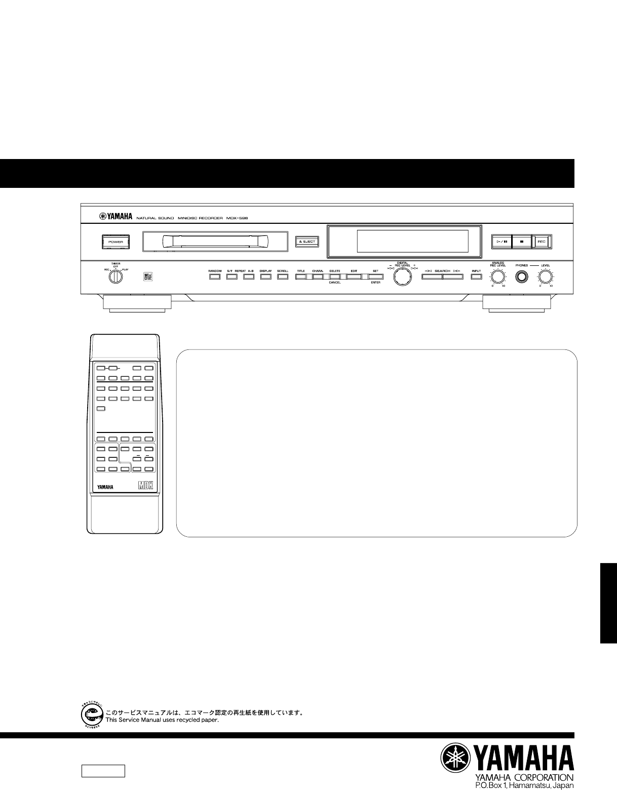
- MINIDISC RECORDER 1
- ■ TO SERVICE PERSONNEL 2
- ■ REAR PANELS 3
- ■ SPECIFICATIONS 4
- ■ DISASSEMBLY PROCEDURES 5
- ■ INTERNAL VIEW 5
- Magnetic Head 6
- Leaf Spring 6
- MD Mechanism 6
- Spindle Motor 7
- ■ ADJUSTMENT & TEST MODE 8
- [ TEMP ❍ ❍ ◆ ◆ ] 11
- [ TEMP 7A 79 ] 11
- Push down with a finger 14
- MECHANISM ADJUSTMENT 15
- EEPROM CONTENTS LIST 17
- ■ SPECIAL TEST MODE 18
- ■ ERROR DISPLAY 19
- Mechanism Error 20
- ■ TROUBLESHOOTING 21
- ■ IC DATA 26
- IC1101 : IR3R58M 27
- RF Signal Processing 27
- IC1201 : LR37814 27
- ATRAC Encoder/Decoder 27
- IC1202 : IX2474AF 30
- 4M Bit D-RAM 30
- IC1402 : 58X2402T 30
- IC1401 : iX0324AW 31
- MD System Microprocessor 31
- IC1701 : UDA1347T 33
- AD Converter/DA Convereter 33
- IC6 : M30622M8-xxxFP 34
- Main System Microprocessor 34
- ■ BLOCK DIAGRAM (MD) 36
- ■ BLOCK DIAGRAM 37
- ■ TEST POINT WAVEFORM 38
- ■ PRINTED CIRCUIT BOARD 39
- MAIN (1) P.C.B 40
- MAIN (6) P.C.B 41
- MAIN (5) P.C.B 41
- ■ MD VOLTAGES 42
- MD MAIN PWB-C 43
- E-49/J-47 44
- FL DRIVER 45
- REMOTE CONTROL TRANSMITTER 46
- PARTS LIST 47
- P.C.B. MAIN 48
- P.C.B. MD MAIN 50
- P.C.B. MD MAIN CHIP RESISTORS 52
- EXPLODED VIEW 53
- MECHANICAL PARTS 54
- New Parts 56
- GREASE APPLICATION DIAGRAM 57
- 1/4W Type 58
- 1/6W Type 58
Summary of Contents
MDX-596MDX-596100718SERVICE MANUALMDX-596IMPORTANT NOTICEThis manual has been provided for the use of authorized YAMAHA Retailers and their service pe
MDX-596MDX-596Description of TEST modes1. EJECT mode To TEMP setting (of EEPROM setting)[ _ _ EJECT _ _ _ ] To CONTROL setting (of EEPROM setting)Lase
MDX-596MDX-59610● Confirmation of pick-up laser powerRecording and reproduction can be checked by using the laser power meter. However it should beuse
MDX-596MDX-596113. AUTO adjustment mode Disc in use: TDYS1 (SONY) [for reproduction] or commercially availablemini disc for recordingStep Setting meth
MDX-596MDX-5967. TEST-REC mode Disc in use: Commercially available mini disc for recording (It is used to check the REC function at the specified addr
MDX-596MDX-596● Forced rotation of loading motorIt is possible to force the loading motor to rotate by turning the jog dial when the microprocessor ve
MDX-596MDX-59614Fig. 11MECHANISM ADJUSTMENTWhen making an adjustment, be sure to connect an extension cable for servicing and an expansion P.C.B. as s
15EEPROM SETTING MODE TRANSITION DIAGRAMNote) To return to the SUB MENU or MAIN MENU display of the test mode, press the DELETE/CANCEL button.5. EEPRO
16SLG ❍ ❍ 3E HSL2 ❍ ❍ 10 HSLDLIM ❍ ❍ 7F HSLDLEV ❍ ❍ 12 HSLKLVk ❍ ❍ 55 HSLKLVt ❍ ❍ 2E HSLKLVm ❍ ❍ 55 HSLBKm ❍ ❍ 08 HSLKrio ❍ ❍ 60 HSLKroi ❍ ❍ 68 HSLK1i
MDX-596MDX-596 SPECIAL TEST MODE● How to set to the special test modePress the POWER button while pressing the SET/ENTER button and the STOP button.
MDX-596MDX-59618Can't RECCan't CopyDIGin UnlockTOC FullUTOC ERR RUTOC ERR AUTOC ERR L0 ~ 4Not AudioDisc FullPlayback MDProtectedError on dis
MDX-596MDX-596AC LEAKAGETESTER OREQUIVALENTEQUIPMENTUNDER TESTINSULATINGTABLEWALLOUTLET TO SERVICE PERSONNEL1Critical Components InformationComponent
MDX-596MDX-59619Can' t EditTMP Over!!DISC ERR RDISC ERR SDISC ERR WTOC ERR STOC ERR RU TOC W ERRFOCUS ERRBLANK DISCTOC W ERROREEPROM ERRORError o
MDX-596MDX-59620YESNONOWhen MD fails to operateWhen the objective lens of the optical pickup becomes dirty, MD may fail to operate. Clean the objecti
MDX-596MDX-59621NO▼YESNO▼YES▼YESYES▼YES▼YES▲▲▲ Disc cannot be loaded properly.Does the loading function work properly when a disc is inserted?Does No.
MDX-596MDX-59622▼NO▼YES▲▼▼Normal reproductionApplicable when the E2-PROM value has been confirmed as normal in the test modeIs initialization done pro
MDX-596MDX-59623YES▲▲YESNO▲▼YES▼YES▲Recording/reproduction functionLoad a low reflection disc and after confirming the audio output in the normal repr
MDX-596MDX-59624▼YES▲▲▼YESSpindle motor does not run.Is a correct waveform provided at No.24 and 25 pins of IC1201during the AUTO adjustment mode step
MDX-596MDX-59625 IC DATAMODESWBPFBIASADIP AGCDIFFRESISTOR & SWEFM AGCRF1RF2RF3RF4REFIREFOAOUTASWAINBINBSWBOUT2-1ADAGIADAGCADIPNFADIPOGND2WBOVCC2O
MDX-596MDX-59626The * marked terminal is a terminal which is not connected externally (open terminal).No. Pin Name33* ADIPNF34 ADAGC35 ADAGI36 2-137 E
MDX-596MDX-59627No. Pin Name I/O10 BIN I11 EIN I12 FIN I13 VBAT I14 VDD115 DGND16 TEST2 I17* X176KO O18 FODRF O19 FODRR O20 TRDRF O21 TRDRR O22 SLDRF
MDX-596MDX-59628No. Pin Name I/O65 XO O66 DIN I67 DOUT O68 PLLBVG O69 DGND70 LRCK O71 BCLK O72 DFCK O73 ADDATA I74 DADATA O75* FEMON O76* TOTMON O77*
MDX-596MDX-5962 REAR PANELS▼ R model▼ G, B models▼ A modelVARO! : AVATTAESSA JA SUOJALUKITUS OHITETTAESSA OLET ALTTIINA NÄKYMÄTTÖMÄLLELASER-SÄTEILYL
MDX-596MDX-59629Pin No. Name Function1, 2 DQ0, DQ1 Data input/data output3 WE Write enable4 RAS Low address strobe5 A9 Address input6 — 9 A0-A3 Addres
MDX-596MDX-59630No. Pin Name I/O1 4M/16M O2 64M O3 LDVAR O4* ADJS O5 CIN I6* NC7 UNLOCK I8 BYTE I9 CNVss I10* STID OUT O11* SEACH OUT O12 RESET I13* N
MDX-596MDX-59631No. Pin Name I/O55* P37 O56* P36 O57* P35 O58* P34 O59* P33 O60* P32 O61 P31 O62 Vcc I63 INNSW I64 GND65 L3 DATA O66 L3 MODE O67 L3 CL
MDX-596MDX-59632Pin No. Name Function1 VSSA(ADC) ADC analog ground2 VDDA(ADC) ADC analog power supply3 VINL ADC input (left)4 Vref(A) ADC reference vo
MDX-596MDX-59633IC6 : M30622M8-xxxFPMain System MicroprocessorNo. Port I/O Name1 P96/ANEX1 I/O2 P95/ANEX0 I/O3 P94/DA1 I/O4 P93/DA0 I/O5 P92/TB2in O D
MDX-596MDX-59634No. Port I/O Name40 P56/ALE I/O41 P55//HOLD I FLASH_GND42 P54//HLDA O POWERDOWN43 P53/BCLK I/O44 P52//RD I/O45 P51//WRH,/BHE I/O46 P50
MDX-596MDX-59635 BLOCK DIAGRAM (MD)12345678910111213141516171819202122232425262728D GNDD GNDRESETMD-STDSCKKDATAMDDATADSTBD GNDD GNDDVDDDVDDPCONTOLOAD
ABCDEFGH123456MDX-596 BLOCK DIAGRAME-37/J-35IC6 CPUM30622M8-XXXFPDISPLAY DRIVEIC601MUTECONTROLQ8,D3,4,6DISPLAYV601Q4Q6Q5Q7PHONESINPOWER SWSW401L302FL
ABCDEFGH123456MDX-596 TEST POINT WAVEFORME-38/J-36POWER ONTOC READ(Low reflection disc)TOC READ(Low reflection disc)TOC READ(Low reflection disc)PLAY
ABCDEFGH123456MDX-596 PRINTED CIRCUIT BOARDq to #3: TEST POINT WAVEFORMS (See page E38/J36)E-41/J-39C1616 XL1201IC1101CN1101IC1202IC1201IC1601CN1401I
MDX-596MDX-5963 SPECIFICATIONSUnits : mm (inch)265.9 (10–1/2")287.8 (11–5/16")15.2(5/8")6.7(1/4")435 (17–1/8")16(5/8")8
ABCDEFGH123456MDX-596Point q (Pin 13 of IC6)V : 2V/div H : 20 µsec/divDC range 1 : 1 probePoint wCH1 : Emitter of Q2CH2 : Collector of Q14V : 2V/div C
ABCDEFGH123456MDX-596 PRINTED CIRCUIT BOARD (Foil side)E-45/J-43FL2FL1AC2GNDAC1L301W301#8TO : MAIN(1)W302#401TO : MAIN(4)MAIN (3) P.C.B.FROM : POWER
PRINTED CIRCUIT BOARDABCDEFGH123456MDX-595E-46/J-44CN1932SW1936LEAD INMD MECHANISMSWITCH PWB-E1M901MD SPINDLE MOTORM902MD SLED MOTORORBL16CN1402TO M
ABCDEFGH123456IJK78NDX-596 SCHEMATIC DIAGRAM12345671016301718192223242521272831292026323314151213TP1630TP1303TP1130TP1415TP1213TP1136TP1422TP1421TP14
ABCDEFGH123456IJKL78MDX-596* All voltages are measured with a 10MΩ/DC electric volt meter.* Components having special characteristics are marked Z and
ABCDEFGH123456IJK78NDX-596* All voltages are measured with a 10MΩ/DC electric volt meter.* Components having special characteristics are marked Z and
ABCDE1234567MDX-59651 SCHEMATIC DIAGRAMREMOTE CONTROL TRANSMITTERR12.2ΩKI/O8KI/O7SOREMVDDXOUTXINVSSKI/O5KI/O4KI/O3KI/O2KI/O1KI/O0KI3KI2KI1KI012345678
MDX-596MDX-59652ABBREVIATIONS IN THIS LIST ARE AS FOLLOWS :C.A.EL.CHP : CHIP ALUMI. ELECTROLYTIC CAPC.CE : CERAMIC CAPC.CE.ARRAY : CERAMIC CAP ARRAYC.
MDX-596MDX-596SchmRef. PART NO. DescriptionNew Parts*SchmRef. PART NO. DescriptionNew Parts*53P.C.B. MAIN* V5731000 P.C.B. MAIN(R)* V5731100 P.C.B. MA
MDX-596MDX-596SchmRef. PART NO. DescriptionNew Parts*SchmRef. PART NO. DescriptionNew Parts*54P.C.B. MAIN* D5 VG437600 DIODE.ZENR MTZJ5.6A 5.6V* D6 V
MDX-596MDX-596 DISASSEMBLY PROCEDURES(Remove parts in disassembly order as numbered.)Fig. 24 INTERNAL VIEW1. Removal of Top Covera. Remove 4 screws
MDX-596MDX-59655P.C.B. MD MAINSchmRef. PART NO. Description RemarksSchmRef. PART NO. Description Remarks*New Parts*New PartsP.C.B. MD MAINC1100 AAX025
MDX-596MDX-59656P.C.B. MD MAINSchmRef. PART NO. Description Remarks*New PartsSchmRef. PART NO. Description Remarks*New Parts* IC1201 AAX17310 IC LR378
MDX-596MDX-59657P.C.B. MD MAIN CHIP RESISTORSSchmRef. PART NO. Description Remarks*New PartsSchmRef. PART NO. Description Remarks*New PartsR1463 AAX01
ABCDE1234567MDX-596 EXPLODED VIEW58251-3244484828262004522(5)4924494792241434112434345434343212(7)292(1)4630234527422(3)11472(4)252(2)1-111-241-321-2
MDX-596MDX-596 MECHANICAL PARTSRef.No. PART NO. Description Remarks MarketsNew Parts*591-5 MF119200 FLEXIBLE FLAT CABLE 19P 200mm* 1-11 V5235500 FRON
ABCDE1234567MDX-59660 EXPLODED VIEW (MD Recorder Unit)741252SW1934SW1933SW1932SW1931SW1930179M9033PWB-E1SW1936M902504342728141550335M901507501x224507
MDX-596MDX-596Ref.No. PART NO. Description Remarks MarketsNew Parts*61 MECHANICAL PARTS (MD Recorder Unit)V5063300 MD RECORDER UNIT V5063300* 2 AAX16
ABCDE1234567MDX-59662GREASE APPLICATION DIAGRAMGreaseG : Molykote PG-662O : HYDRO-FLUTE EP-68745293M9022721181022GGGGGGGGGGOG
Parts List for Carbon Resistors1/6W Type Part No.HF45 7100HF45 7110HF85 7120HF45 7130HF45 7150HF45 7180HF45 7220HF45 7240HF85 7270HF45 7300HF45 7330HF
MDX-596MDX-596
MDX-596MDX-5965Disassembly of MD Recorder UnitRemove the MD Recorder unit according to Steps 1 and 3 of the disassembly procedure (page 4).Removal of
MDX-596MDX-5966Fig. 5Removal of MD Loading P.C.B./Loading Motor (Fig. 5)1. Remove 1 screw (B1).2. Remove 3 hooks (B2) and then remove the MDLoading P.
MDX-596MDX-5967TEST MODE1. How to enter the test mode1) Press the POWER button while pressing the SET/ENTER button and the PLAY/PAUSE button.Version o
MDX-596MDX-59683. How to cancel test mode (Entry of EEPROM adjustment value)1) Be sure to perform AUTO preliminary adjustment, AUTO adjustment and AUT
More documents for CD players Yamaha MDX-9

Related products and manuals for CD players Yamaha MDX-9
 (28 pages)


 (26 pages)
(16 pages)
(18 pages)
(82 pages)
(26 pages)
(16 pages)
(18 pages)
(82 pages)
 (46 pages)
(36 pages)
(52 pages)
(4 pages)
(46 pages)
(36 pages)
(52 pages)
(4 pages)

 (242 pages)
(18 pages)
(31 pages)
(28 pages)
(14 pages)
(4 pages)
(32 pages)
(18 pages)
(242 pages)
(18 pages)
(31 pages)
(28 pages)
(14 pages)
(4 pages)
(32 pages)
(18 pages)
© 2020, manymanuals.com. All rights reserved. | 1.377 s |
 Manymanuals.com
 Manymanuals.de
 Manymanuals.fr
 Manymanuals.it
 Manymanuals.pl
 Manymanuals.cz
 Manymanuals.es
 Manymanuals-pt.com
Comments to this Manuals