)
[PEAK] LED
Lights when the volume of input sound is too high. If it is lit,
turn the [GAIN] knob
!
to the left to lower the volume.
!
[GAIN] knob
Determines the basic volume for channel 1. Adjust this knob
so that the [PEAK] LED
)
flashes briefly when singing or
playing the loudest.
@
[COMP/EQ] button*
This button turns on the compressor and equalizer (yellow
LED lights). The default settings reduce unwanted low-
frequency noise and variations in vocal level, and have
parameters that are suitable to webcasting.
#
[EFFECT] button*
This button turns on the effects on channel 1 (yellow LED
lights). The default settings have reverb turned on to add a
natural spaciousness to the sound.
$
Fader
%
Level knobs
Set the volume balance between each channel.
: Adjust the volume of the sound input from the microphone
or other source connected to channel 1.
: Adjust the volume of the sound input from the guitar,
electric keyboard, or other source connected to channel 2.
: Adjust the volume of the sound input from the computer via
the [USB 2.0] terminal.
1
2
3
5
)
!
4
%
^ &
B
A
C
D
H
E
F
G
$
6
8
7
9
(
*
@
#
Front panel
3
Set the fader and all knobs ([GAIN] knob, Level knobs, Speakers [ ] knob, and
Headphones [
] knob) to the minimum.
(Minimum: Lower fader to the bottom setting. Turn knobs fully to the left.)
[GAIN] knobs
Level knobs
Fader
Speakers [
] knob
Headphones [
] knob
4
Make sure that the volume of the powered speakers is set to minimum.
5
Turn on the power to connected devices in the following order: Instruments,
audio devices
Mixer's [ ] switch Powered monitor speakers.
NOTICE
Follow this order to avoid loud, unexpected noise from the speakers. Reverse the order when
turning the power off.
6
If a microphone or instrument is connected to channel 1, set the [GAIN] knob to
the 12 o'clock position.
7
Slide the fader to the position indicated by the thick line, and turn the Level
knobs to the 3 o'clock position.
8
Set the Speakers [ ] knob and the Headphones [ ] knob to the 12 o'clock
position.
9
Speak into your microphone, play your instrument, or play your audio device,
and adjust the volume on the powered monitor speakers.
10
If no sound is heard, of if you want to adjust the volume, follow the instructions
in the boxed section below.
If you still do not hear the sound after doing the following steps, please refer to the
checklist in the "Troubleshooting" section at the back of this booklet.
n
There is no sound, or you need to increase the volume
1
Speak into your microphone or play your instrument, turning the [GAIN]
knob to the right so that the corresponding [PEAK] LED flashes briefly.
NOTE
• For optimum volume when using a microphone, place the microphone as close to the sound source
as possible.
• If the [PEAK] LED does not light even if the [GAIN] knob has been turned fully to the right, raise the
volume of the sound source (instrument, etc.).
If no sound is heard or the volume does not increase after step 1:
2
If the [PAD] switch or [GAIN] switch is turned on (
O
), set the fader and Level
knob fully to minimum, and then turn off (
N
) the switches.
3
Slowly slide the fader or turn the Level knob until the desired volume is
reached.
n
To decrease the volume:
1
Set the fader and the Level knob fully to the minimum, and then turn on
(
O
) the [PAD] switch or [GAIN] switch on the channel for which you want to
decrease the volume.
2
Slowly slide the fader or turn the Level knob until the desired volume is
reached.
If the volume does not decrease after the above steps:
3
Lower the volume of the instrument or audio device.
Welcome
Thank you for purchasing the Yamaha AG03 Mixing Console. Please read this manual
thoroughly to get the most out of the product and ensure long-term, trouble-free use. After
reading this manual, keep it readily available for future reference.
For the remainder of this manual, the word "mixer" is used instead of "Mixing Console."
Main Features
Multi-purpose 3-channel mixer with audio interface, ideal for live webcasting
• Audio interface supports up to 24-bit/192 kHz recording.
• An intuitive Loopback function enables fast and easy live webcasting.
• Yamaha's premium “D-PRE” mic preamp provides high resolution sound.
Included Accessories
• USB cable (1.5 m)
• Technical Specifications (English only): Includes general specifications, input/output characteristics,
block diagram, dimensions, and jack and plug list.
• CUBASE AI DOWNLOAD INFORMATION: Contains the access code necessary for downloading the
Steinberg DAW software Cubase AI.
• Owner's Manual (this leaflet)
Quick Start Guide
Preparation: Download and install drivers.
The "Yamaha Steinberg USB Driver" might be required for computer input/output. Visit the
following Yamaha website for details on downloading and installing the driver, and making
the necessary settings.
http://www.yamahaproaudio.com/ag/
STEP 1 Connecting speakers, microphones,
instruments, etc.
1
Turn off the power of all speakers, instruments, and other devices to be
connected to the mixer.
2
Connect speakers, microphones, and instruments referring to the connection
example below.
Connection Example
Microphones
Electric guitar
Electric keyboard
Powered
monitor
speakers
Headphones
Audio device
Headset
Smartphone
Foot switch
(Yamaha FC5)
Computer
Rear panel
NOTE
If you are using condenser microphones, turn on (
O
) the [+48V] phantom power switch.
STEP 2 Getting sound to the speakers or headphones.
1
Make sure that all switches including the [ ] (Standby/On) switch are not
pressed (
N
).
2
Use the included USB cable to connect your computer to the mixer.
When using the [USB 2.0] terminal on the mixer's rear panel, refer to the notice
"Precautions when using the [USB 2.0] and [5V DC] terminals." When connecting a
tablet or other device that cannot provide power to the mixer, connect a commercially
available USB power adapter or USB mobile battery to the [5V DC] terminal (micro B).
ZN42690
MIXING CONSOLE
EN
Owner’s Manual
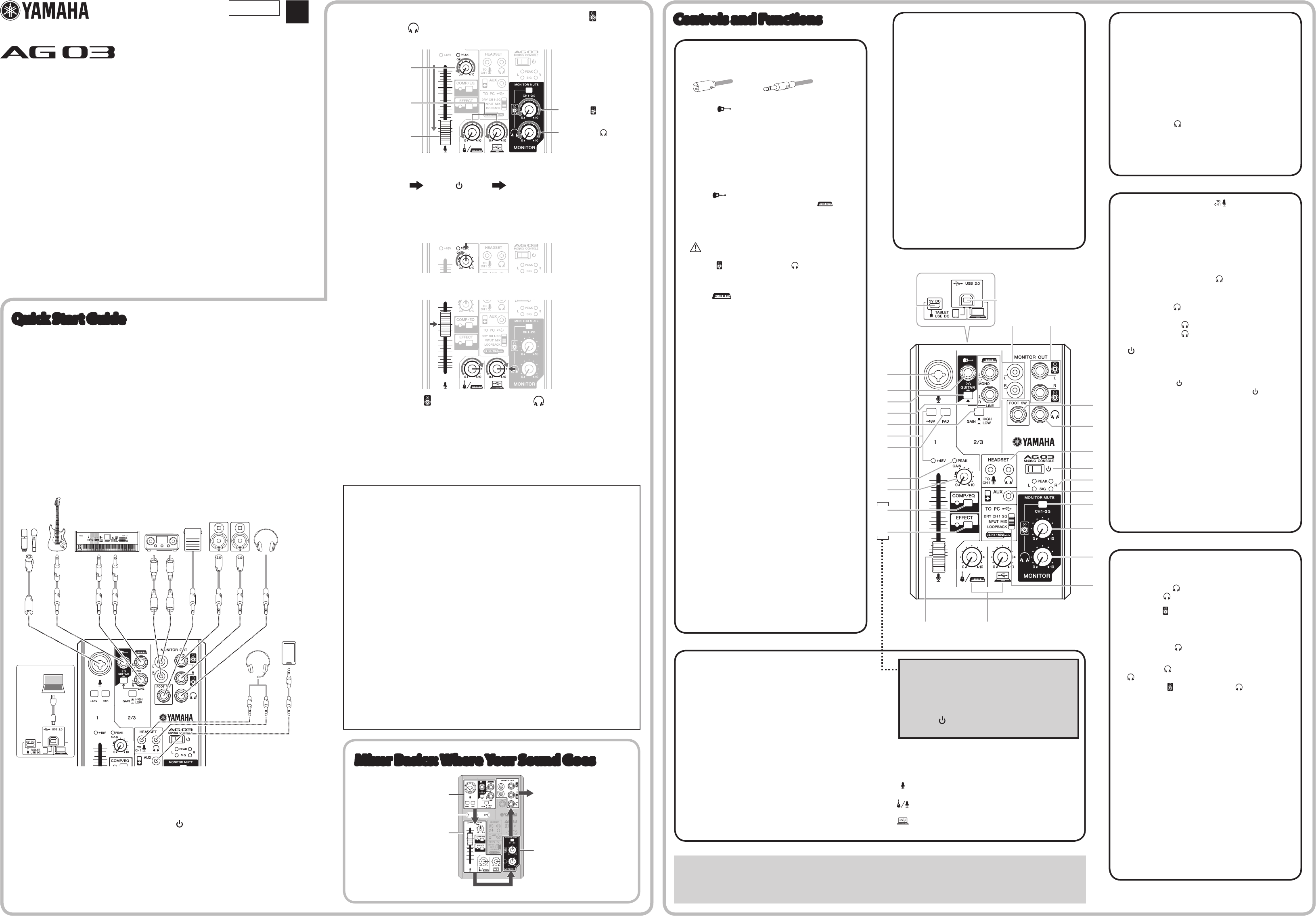
Controls and Functions
A
[HEADSET] microphone [ ] input jack
For connecting to the microphone plug for your headset.
Normally this plug is color-coded in pink. The audio input here
is sent to channel 1.
NOTE
If a microphone is connected to the [HEADSET] microphone
input jack, the sound from the microphone or instrument
connected to the MIC/LINE input jack
3
on channel 1 is cut
off.
[HEADSET] headphones [ ] output jack
For connecting to the headphone for your headset. Normally
this plug is color-coded in light green. The same sound as for
the headphones [
] output jack
(
is output.
NOTE
If a headphone plug is connected to the [HEADSET]
headphones [
] output jack, the sound output from the
headphones [
] output jack
(
is cut off.
B
[ ] (Standby/On) switch
For turning the power of the unit to standby (
N
) and on (
O
).
NOTICE
Rapidly switching the [ ] switch between on and standby in succession
can cause the mixer to malfunction. After switching the [
] switch to
standby, wait for at least six seconds before turning it on again.
C
Level meter
If the level of the sound sent to the computer exceeds -10
dBu, [SIG] (green) turns on; if the level reaches 3 dB before
clip level (+7 dBu), [PEAK] (red) turns on. To send an
appropriate volume to the computer, adjust the volume of
each channel until [SIG] remains lit and [PEAK] flashes only
momentarily when there is a loud sound.
D
[AUX] input jack
This is an auxiliary input jack. It supports a stereo mini plug.
You can connect a smartphone or other device and use
applications to trigger sound effects or background music.
Use the controls on the connected device to adjust volume.
E
[MONITOR MUTE] switch
When this switch is on (
O
), sound input to channels 1
and 2G is not output from the [MONITOR OUT] jacks
^
&
, headphones [
] output jack
(
, and [HEADSET]
headphones [
] output jack
A
(direct monitoring is OFF).
F
Speakers [ ] knob**
Adjust the volume sent to the device connected to the [MONITOR
OUT] jacks
^
&
.
G
Headphones [
] knob**
Adjust the volume to headphones connected to the
Headphones [
] output jack
(
and [HEADSET] headphones
[
] output jack
A
.
** The Speakers [ ] knob and Headphones [ ] knob can be
adjusted separately.
H
[TO PC] slide switch
Select the sound to send to the computer.
[DRY CH 1-2G]:
Sends the sound after [GAIN] knob adjustments from channel
1 and the sound immediately after the [GAIN] switch from
channel 2G directly to the computer. The sound that is sent is
not affected by Level knob adjustments. The sounds input to
channels 1 and 2G (guitar and vocal, etc.) can be recorded
separately, as with an audio interface.
[INPUT MIX]:
The sound input into the mixer and mixed in stereo is sent to
the computer. Sound input from the computer is not sent back
to the computer.
[LOOPBACK]:
The sound input into the mixer and the sound played on the
computer are mixed in stereo and sent to the computer. This
setting is used primarily for webcasting.
NOTE
To prevent feedback when using DAW software, use either
[DRY CH1-2G] or [INPUT MIX].
3
MIC/LINE input jacks
For connecting to a microphone, an instrument, or an audio
device. These jacks support both XLR and phone plugs.
XLR Phone
4
Guitar [
] input jack (channel 2G)
For connecting to an instrument, such as an electric
guitar or an electric bass. This jack support phone plugs.
This jack is disabled when the [GUITAR/LINE] switch
5
is off (
N
).
5
[GUITAR/LINE] switch
For switching the input on channel 2. Turn this switch on
(
O
) when directly connecting an instrument with high output
impedance, such as an electric guitar or electric bass, to the
Guitar [
] input jack
4
. Turn this switch off (
N
) when
connecting a line-level instrument to the Line [
] input
jack
6
. When this switch is turned on, use an unbalanced
cable with phone plugs to connect the instrument to the mixer.
The mixer will not operate correctly if a balanced cable is
used.
CAUTION
When operating this switch, turn all output controls (such as the
Speakers [
] knob
F
and Headphones [ ] knob
G
) fully to "0"
(minimum). Sudden high level peaks caused by the switching operation
can damage external devices as well as the hearing of those present.
6
LINE [ ] input jacks
For connecting to line-level devices such as an electric
keyboard or an audio device. Use the [L/MONO] jack on
channel 2 for instruments, etc. with mono output. In this case,
the sound input to the [L/MONO] jack is output from both the
L channel and R channel on the mixer. This jack is disabled
when the [GUITAR/LINE] switch
5
is on (
O
).
7
[GAIN] switch
Determines the basic volume for channel 2/3. Turn this switch
on (
O
) if you hear distortion.
NOTE
Turn the Level knob to minimum before turning the [GAIN]
switch on (
O
) and off (
N
). Otherwise, noise may be
produced.
8
[+48V] phantom switch / [+48V] LED
When this switch is turned on (
O
), the [+48V] LED lights and
DC +48 V phantom power is supplied to the XLR plug on MIC/
LINE input jack
3
. Turn this switch on when using a phantom-
powered condenser microphone.
NOTICE
Be sure to leave this switch off (
N
) if you do not need phantom power.
Follow the important precautions below, in order to prevent noise and
possible damage to external devices as well as the mixer if you turn this
switch on (
O
).
• Be sure to leave this switch off (
N
) when you connect a device that
does not support phantom power to channel 1.
• Make sure to turn this switch off (
N
) when connecting/disconnecting
a cable to/from channel 1.
• Slide the fader on channel 1 to minimum before turning this switch on
(
O
)/off (
N
).
9
[PAD] switch
Turning the switch on (
O
) will attenuate the sound input to
channel 1. If you hear distortion or the [PEAK] LED
)
lights
frequently even if the [GAIN] knob
!
is turned fully to the left,
turn this switch on.
NOTE
Slide the fader to minimum before toggling the [PAD] switch
on (
O
) and off (
N
). Otherwise, noise may be produced.
1
[USB 2.0] terminal
For connecting to a computer using the included USB 2.0
cable. When connected to a computer, the computer supplies
power to the mixer and audio data can be sent between
the mixer and computer. A USB driver might be required for
computer input/output. You can download the driver from the
following Yamaha website, and install it on your computer.
http://www.yamahaproaudio.com/ag/
NOTICE
Please do not connect any device to [USB 2.0] terminal other than
personal computers or tablet devices.
2
[5V DC] terminal
For connecting to a commercially available USB power
adapter or USB mobile battery. Use this terminal when
connecting the mixer to a tablet or other device that cannot
supply power to the mixer. A USB power adapter or USB
mobile battery is not included with the mixer.
NOTICE
• Please read the safety precautions for the USB power adapter or
USB mobile battery that you are using.
• Use a USB power adapter or USB mobile battery that can supply
power via a USB micro B plug based on the following USB standards:
Output voltage: 4.8 V to 5.2 V
Output current: 0.5 A or greater
* You can use a dedicated application to set the detailed
settings for [COMP/EQ]
@
and [EFFECT]
#
. Visit the
following Yamaha website for details.
http://www.yamahaproaudio.com/ag/
n
Resetting
@
and
#
to factory default settings
Turn the [ ] switch
B
on (
O
) while pressing and holding
down the [COMP/EQ] button
@
.
Rear panel
n
Tips on volume adjustment
Use the [PAD] switch, [GAIN] knob/[GAIN] switch, and fader/Level knobs to adjust volume. However, the [PAD] switch and [GAIN] knob/[GAIN]
switch should not be adjusted again once they have been set optimally. Normally, the fader/Level knobs are used to adjust volume. For details
about each function, see "Controls and Functions".
Mixer Basics: Where Your Sound Goes
1
Input the sound from a
microphone or instrument
2
Adjust the volume, tone,
and effects of each channel.
3
The sound from all
channels ows rightward
5
Output the sound from
speakers or headphones
4
Final adjustment of the
volume of the mixed sound
Channel number
^
[MONITOR OUT] jacks (RCA jacks)
&
[MONITOR OUT] jacks (phone jacks)
Connect powered monitor speakers. These jacks support
phone plugs (balanced/unbalanced).
*
[FOOT SW] jack
For connecting to a separately-sold foot switch (Yamaha FC5,
etc.).
When the [EFFECT] button
#
is turned on, the effected sound
can be muted with a foot switch. The [EFFECT] button LED
flashes while the effected sound is muted.
(
Headphones [ ] output jack
For connecting to a set of headphones. This jack supports a
stereo phone plug. To connect headphones or earphones with
stereo mini plugs, you can use the [HEADSET] headphones
output jack
A
.

 (14 pages)
 (2 pages)
 (50 pages)


 (24 pages)
 Manymanuals.com
 Manymanuals.de
 Manymanuals.fr
 Manymanuals.it
 Manymanuals.pl
 Manymanuals.cz
 Manymanuals.es
 Manymanuals-pt.com
Comments to this Manuals